Learn to use an optocoupler or opto-isolator
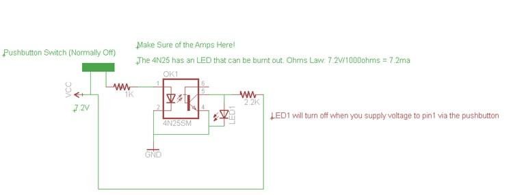
Optocoupler or opto-isolators are cool little devices that allow you to completely separate parts of a circuit. As I understand it, MIDI protocol requires the use of optocoupler in all devices. I wanted to use an optocoupler to separate the USB (5V) powered circuit from the 7.2VRCCar battery powered circuit. The idea behind this was that I wanted to protect the USB-based circuit from high currents, inductors, higher voltages, and other things that happen on the RCCar side of that circuit, but still want to be able to control it using USB devices. After successfully using a Fairchild 4N25 opto-coupler to transfer pulse width modulation from the USB-based circuit to the 7.2V circuit to control the server.
The Fairchild Semiconductor 4N25SM, despite the surface mount, has a large enough pin spacing that you can easily solder wires directly to the pins for experimentation. I built a breakout board for this part and found after a week that the optocoupler was not performing as well as it should. I think the pins of the optocoupler were overheating when they were soldered to the branch board.
In all configurations of the 4N25. I have always seen the output connected in parallel with the transistor side collector (pin 5). the transistor side of the 4N25 (pins 4. 5 and 6) reproduces the signal by always being high, unless the LED is lit. When the LED in the 4N25 is lit, it causes the input and output to go low due to a direct ground path.

When researching work with the 4N25. I always saw schematics where the base was not connected at all, or grounded through a very large resistor in the 100k and above range. Initially, I did not connect the base of pin 6 to anything. However, after sending a pulse width modulated signal through the optocoupler to control the servo, I noticed that the servo would not hold its position without a small amount of back and forth cranking back and forth quickly.
I then hooked a wide range potentiometer between the base of the transistor (pin 6) and ground. As I adjusted the resistance on the base of the transistor from zero to about 80K ohms, I could clearly see the jerk motion on the servos increasing or decreasing, resulting in smooth operation.


